


When designing launchers for small-caliber underwater vehicles, it is also necessary to take into account the fact that, due to their shorter length compared to traditional naval weapons, such products experience large accelerations at the same exit speed from the launcher. This makes it practically impractical from the point of view of the weight and size characteristics of the product to implement the starting pulse in the form of a point application of force (for example, when using a sliding pusher).
Below, as an example, the design of such a TPK, designed for basing torpedoes, missiles, anti-torpedoes on submarines and large-displacement UUVs, will be given.
1.3 Possible design of TPK for basing weapons on submarines and NPA
The design described below uses compressed air energy as an independent energy for ejecting products. In connection with this circumstance, their designs provide for the presence of separate elements (high-pressure air regulators) that control the flow of compressed air depending on the depth at which the apparatus is ejected.
The features of this design are a simplified design of the device, as well as a reduced spread of the output speed of the produced underwater vehicle in a wide range of depths of use of the device. The proposed design is shown in Fig. 5, which shows the general arrangement of the TPK and in fig. 6, which shows a section of the main valve line and the ball valve located in it.
On fig. 5 shows a general view of the structure in section, in which the underwater vehicle 1 is placed in the launch tube 2, bored out for the piston 3, with the obturator ring 4 fixedly installed in its front part, forming a damping cavity 5 with the inner surface of the launch tube, in size consistent with the annular plunger 6 piston 3.
The underwater vehicle rests with its head on obturator ring 4, and with shuttles 7 on grooves 8. During transportation and storage in the longitudinal direction, the movement of the apparatus is limited by an annular buffer 9 and a bursting disc 10, which seals the inner volume of the launch tube 2 filled with inhibitor. Initial fixation of the piston 3 from turning relative to its longitudinal axis is provided by stops 11.
On the other side of the pipe 2, the section including the cylinder 12 is hermetically docked to form an expansion chamber 13. On the end wall of the cylinder 12, which limits the expansion chamber 13, the main valve 14 is placed, in the outlet line 15 of which a ball valve 16 is installed, which interacts with a remotely controlled stepping motor 17 , which changes its flow area during rotation.
In the tide 18 of the outer end of the receiver 12 there is a piston of the pneumatic drive for opening the main valve 14. In the piston 19 of the drive pressed by the spring 20, a socket 22 of the receiver air filling system connected with the internal volume of the receiver is formed by a channel 21. To control the operation of the pneumatic drive, a small-section starting pneumatic valve 23 with an electromagnetic drive is provided.
The dotted line on the sketch shows a hermetic cap 24, which ensures the transport safety of the device.
Figure 5 – Longitudinal section of the TPK On fig.
Figure 6 shows a section of the main valve line and the ball valve located in it, on which the expansion chamber 13 is indicated, in which the outlet line 15 of the main valve 14 is located, in which the ball valve 16 is installed. container.
At the cooking base, high-pressure air is filled into the cylinder 12 through the socket 22 through the channel 21. Due to the difference in sealing areas with the drive piston 19, the main valve 14 will be pressed against the seat in addition to the force of the spring 20, which ensures the reliability of the sealing of the cylinder.
After the transport and launch container is installed on the carrier and the latter enters the sea, at a depth, the underwater vehicle 1 will be in the liquid with the addition of an inhibitor under outboard pressure due to the low rigidity of the membrane 10.
Before the launch of the underwater vehicle 1, it is prepared, during which data from the information and control system of the carrier are entered into it using a device not shown in the drawings. At the same time, via an adjacent cable, also not shown in the drawings, a voltage is applied to the stepper motor 17, causing it to rotate, transmitted to the ball valve 16, which leads to a change in its flow area. In this case, the rotation angle of the ball valve 16 is selected by the information and control system based on the current value of the carrier immersion depth. At minimum depth, ball valve 16 rotates so that its small bore provides low air flow from cylinder 12 to expansion chamber 13. At maximum depth, ball valve 16 remains fully open for maximum air flow.
The implementation of the launch of the underwater vehicle 1 is performed by supplying power to the drive of the pneumatic valve 23. The piston 19 of the drive of the main valve 14 moves it to the open position by air pressure. Through the open main valve 14, high-pressure air from the cylinder 12 enters the outlet line 15, and then, through the passage section of the ball valve 16, into the expansion chamber 13, providing an increase in pressure in it above the outboard one. At the same time, at a shallow depth of immersion of the carrier, the outboard pressure is small, and therefore the air flow required to overcome it is small. At great depths, the opposite is true. Due to the pressure in the expansion chamber, the piston 3 moves along the launch tube and compensates for the loss of water through the obturation, thereby ensuring the movement of the underwater vehicle 1 accelerated relative to it, due to the fact that the area of the piston 3 is larger than the area of the calibrated part of the underwater vehicle located on section of the ring 4 obturations.
In the process of moving piston 3, the air pressure in the expansion chamber 13, due to an increase in its volume, drops, thereby reducing the force acting on piston 3. At the same time, at a shallow depth, this pressure drop is compensated by a small air flow, and at a large one, by a significant one. The preliminary setting of the flow section of the ball valve 16 allows you to adjust the air flow depending on the depth of the carrier immersion, at which the submersible vehicle 1 is ejected.
At the end of the acceleration of the underwater vehicle 1, the piston 3 slows down and then stops, since the plunger 6 compresses the liquid in the damping cavity 5, gradually squeezing it out under the resulting increased pressure through the section decreasing with the movement of the piston. 2 Description of the mathematical model of PU
In the course of this work, a zero-dimensional approach was used. Zero-dimensional (thermodynamic models) use assumptions about the possibility of averaging gas parameters over the internal volume of the combustion chamber (velocities of combustion products and derivatives of gas-dynamic parameters with respect to spatial coordinates are neglected). In this case, it also becomes necessary to make assumptions specifying the heat exchange of combustion products with the walls (the physical principle of the impact and the contribution of various components of the heat flow to its total value). Averaging the gas-dynamic parameters over the chamber volume reduces the original problem to the integration of an ODE system with the corresponding initial conditions or a system of algebraic equations. These equations do not have singularities, so their solution is performed by any ODE integration method. Velocity is calculated using the equations of motion in a one-dimensional formulation.
The advantage of zero-dimensional models is their simplicity, which makes it possible to obtain closed calculated relations. The use of zero-dimensional models is limited by the impossibility of accurately finding the distributions of velocity and other parameters over the intra-chamber volume. There is an accumulation of errors associated with the determination of heat fluxes. The error becomes significant when studying processes in short-term engines (their operation is determined by wave processes in the combustion chamber).
In the calculation part of this work, we accept the assumption that the entire mass of the gas is concentrated in volumes, and the entire kinetic energy is concentrated in the channels.
For the calculation, it is necessary to set several differential equations (change in mass and change in energy in each volume) and the equation of state.
For the calculation, it is necessary to create a mathematical model that describes the behavior of gas-dynamic parameters in the Pascal ABC software environment using differential equations and the equation of state. To do this, first of all, a product model was schematically compiled (Fig. 7) and all the equations necessary to describe the process in the process of launching a missile/torpedo/anti-torpedo from a launcher were compiled.
Figure 7 – The primary model of the product.
Formulas describing this model: (dm_j)/dt=G_ij-G_jk, (1)
where m_j is the mass of gas in volume j;
G_ij and G_jk are mass flow rates in volumes ij and jk, respectively; (dE_j)/dt=G_ij (C_V T_ij+(v_ij^2)/2)+P_ij V_ij F_ij-P_j V_pj F_pj-G_ik (C_V T_jk (v_jk^2)/2)-P_jk V_jk F_jk, (2)
where C_V= R/((γ-1)) is the molar heat capacity of air in the isochoric process;
R=287 – universal gas constant for dry air;
T_ij and T_jk are the gas temperatures in the respective volumes;
v_ij and v_jk are the gas velocities in the respective volumes;
P_ij and P_jk are the pressures in the corresponding cavities;
V_ij and V_jk are the volumes of the corresponding cavities;
F_ij and F_jk are the cross-sectional areas of the channels; (dP_j)/dt=(G_ij C_p (γ-1))/V_j -(γP_j V_pj F_pj)/V_j -(G_jk C_P T_j (γ-1))/V_j , (3)
where γ = 1.4 is the adiabatic index for air T_j=(P_j V_j)/(m_j R) (4) In the future, for convenience and simplicity of calculations, we switch to a more simplified model, which is shown in Figure 8. Figure 8 – The final model of the product
This scheme includes: VAD; adjustable throttle that changes the area of the flow section depending on the depth of submersion of the submarine or ROV; the object itself is a missile, torpedo or anti-torpedo to protect the submarine.
Since the final scheme differs from the one described above, therefore, slightly different formulas will be used to describe it, namely the mass flow derivative, the values of which depend on the outflow mode, the temperature derivative and the pressure formula, which was obtained from the
Mendeleev-Claperon equation.
Depending on the outflow mode (supercritical or subcritical), either formula 5 or formula 6 will be used to search for mass flow: m ̇g=Fcr P_1 μ((RT_1)/(γ(2/(γ+1))^((γ +1)/(γ-1)) ))^(-1/2), (5)
where F_cr= (πd_k^2)/4 is the effective flow area of the valve section; P_1 – pressure in the cylinder; μ=0.95 – flow coefficient; R=287 – universal gas constant for dry air; T_1 – temperature in the cylinder; γ=1.4 is the adiabatic index for air; m ̇g=(Fcr P_1 μ)/√(RT_1 )P ̅^(1/γ)√(2γ/(γ-1)(1-P ̅^((γ-1)/γ) ) ), (6 ) where P ̅=P_2/P_1 is the current pressure difference; T ̇1=(-T_1Rm ̇g)/(C_Vm_g1 ), (7) where m ̇g is the gas mass flow rate; C_V= R/((γ-1)) – molar heat capacity of air in isochoric process; mg1 is the mass of gas in the cylinder; T ̇2=(m ̇g (C_P T_1-C_V T_2 )-(P_2 F_p v))/(C_V m_g2 ), (8) where C_P=C_Vγ is the molar heat capacity of air in the isobaric process; v is the speed of the piston; T_2 – gas temperature in the installation; P_2 – pressure in the installation; F_p=(πd_p^2)/4 – piston area;
m_g2 is the mass of gas in the volume of the installation; P ̇i=(mгi RT_i)/V_i (9) Pascal ABC software environment is used for calculations. This system of equations cannot be solved analytically, so we will use a numerical method for solving differential equations – the Euler method. Historically, the first and simplest way to numerically solve the Cauchy problem for first-order ODEs is the Euler method. It is based on the approximation of the derivative by the ratio of finite increments of the dependent and independent variables between the nodes of a uniform grid.
Initial data for calculations: used caliber – 125 mm (dp = 0.125 m), volume of HP cylinders – 6 liters (V10 = 610-3 m3), cavity volume in the installation – 2.5 liters (V20 = 2.510-3 m3), maximum allowable external pressure – 11 atmospheres (11105 Pa), object weight – 20 kg, permissible overloads – 70 units. In the course of compiling the program for calculating the necessary parameters, a program was compiled in Pascal ABC (Appendix A), in which the following key formulas were used, in addition to the main ones given above in the description of the final model of the product: P ̅cr=〖(2/(γ+1) )〗^(γ/(γ-1)), (10) where P ̅cr is the critical pressure drop; m_g0i=(P_0i V_0i)/(RT_0i ) (11) x ̈=((P_2-P_in))/m, (12) where P_2 is the pressure in the installation; P_in – pressure of the external environment; m = 20 kg is the mass of the object; V_2=V_20+xF_p, (13) where x ̈ is the acceleration of the object; V_20 – initial installation volume; x – movement of the object; F_p=(πd_p^2)/4 – piston area;
3 Results of the study of gas-dynamic processes in the cavities of air launch systems for underwater objects 3.1 The first series of calculations In the course of the WRC, two series of calculations were performed. The first series was carried out in the entire range of pressures of the external environment, simulating the case when we do not provide for regulation of the flow area. As a result of the calculation work, the parameters of the launch systems were determined, which provide the following values at the maximum pressure of the external environment (11 atm): product speed – 18.9 m/s; maximum longitudinal overload during launch – 68.5 units; maximum pressure in the installation cavity – 22 atm (22105 Pa) These values are provided with the following installation parameters: cylinder volume – 6 liters (0.006 m3) initial pressure in the cylinder – 220 atm (220105 Pa)
Appendix 2 presents the complete results of the program operation related to the first series, that is, without regulation and corresponding to the limit value of the ambient pressure (11 atm).
After that, calculations were carried out for cases when the external pressure decreased to 2 atmospheres with a step of 1 atmosphere. The launch system parameters did not change. The calculation results are shown in Figures 9 – 14. Figure 9 – Graphical dependence of pressure in the cylinder on time Figure 10 – Graphical dependence of pressure in the installation on time Figure 11 – Graphical dependence of mass flow on time Figure 12 – Graphical dependence of object displacement on time Figure 13 – Graphical dependence of the object’s speed on time longitudinal load values. It was also found that the pressure in the cylinder in the absence of regulation of the valve flow area does not depend on the pressure of the external environment. The values of the object exit speeds and maximum longitudinal overloads are presented in Table 1. The graphical dependences of these parameters on the pressure of the external environment are shown in Figure 15.
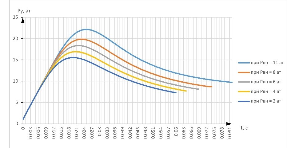
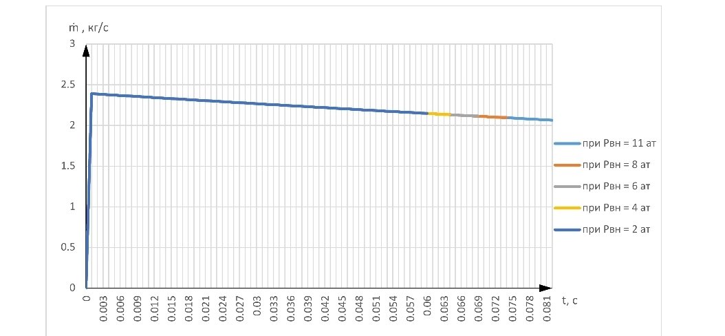
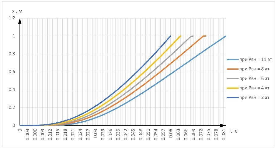
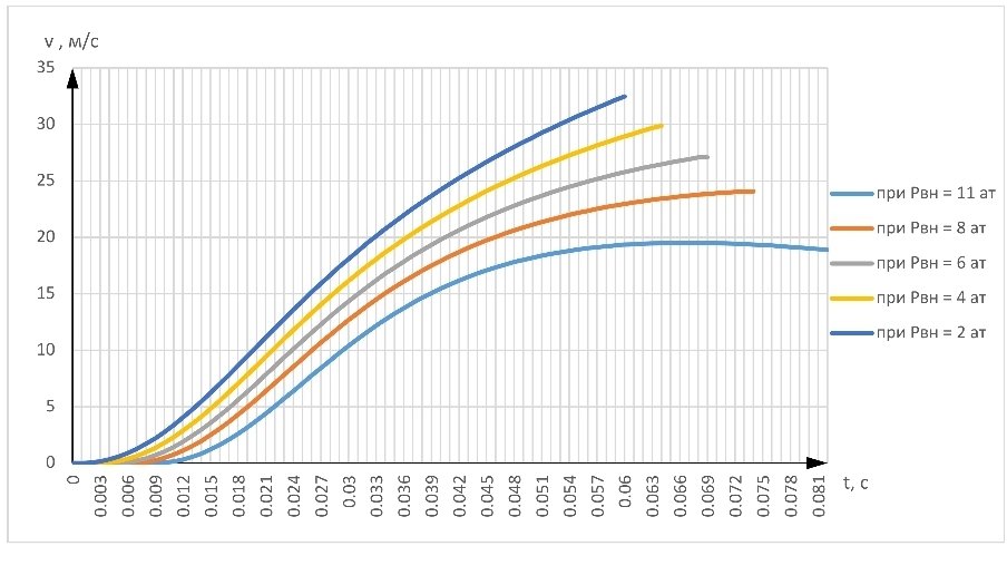
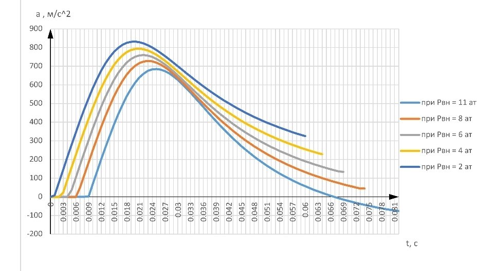
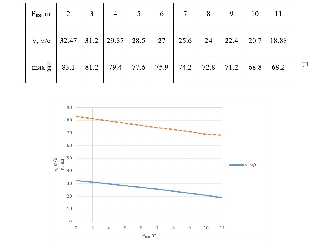
Table 1 – Values of output speed and maximum overloads
Rvn, at 2 3 4 5 6 7 8 9 10 11
v, m/s 32.47 31.2 29.87 28.5 27 25.6 24 22.4 20.7 18.88
max g 83.1 81.2 79.4 77.6 75.9 74.2 72.8 71.2 68.8 68.2
Thus, the results of calculations show that with the value of the effective flow area of the valve section unchanged over the entire range of pressures of the external environment for a given range of pressures of the external environment, it is not possible to provide the same exit speed (about 19 m/s) and an excess of the permissible longitudinal overload is observed (70 units ). 3.2 Second series of calculations
At this stage of calculations, the main task is to find the effective flow area of the valve in the entire pressure range of the external environment. To do this, without changing the values of the initial pressures and volumes in the cylinder and the installation, only the flow area for each pressure of the external environment will change so that the values of the object exit velocity and the maximum longitudinal load correspond to the values obtained during the calculation of the parameters at the maximum pressure of the external environment – 11 atm. The calculation results are shown in Figures 16 – 21.
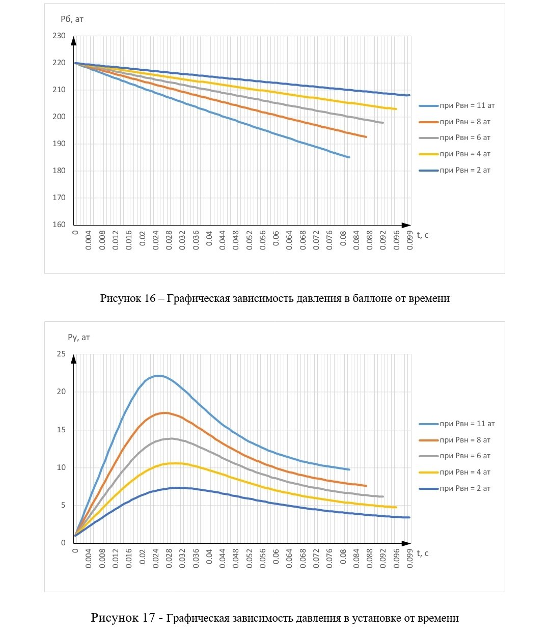
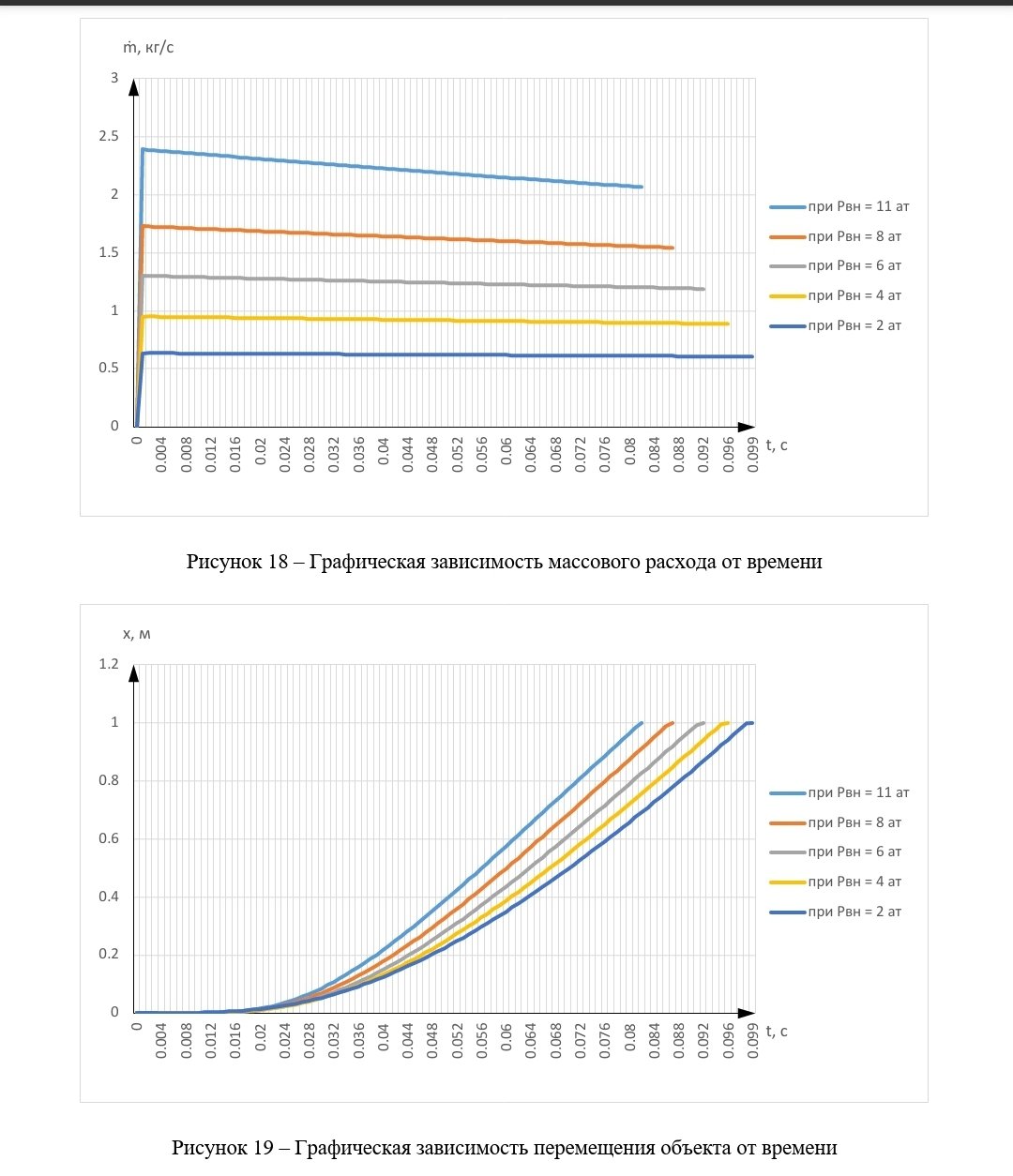
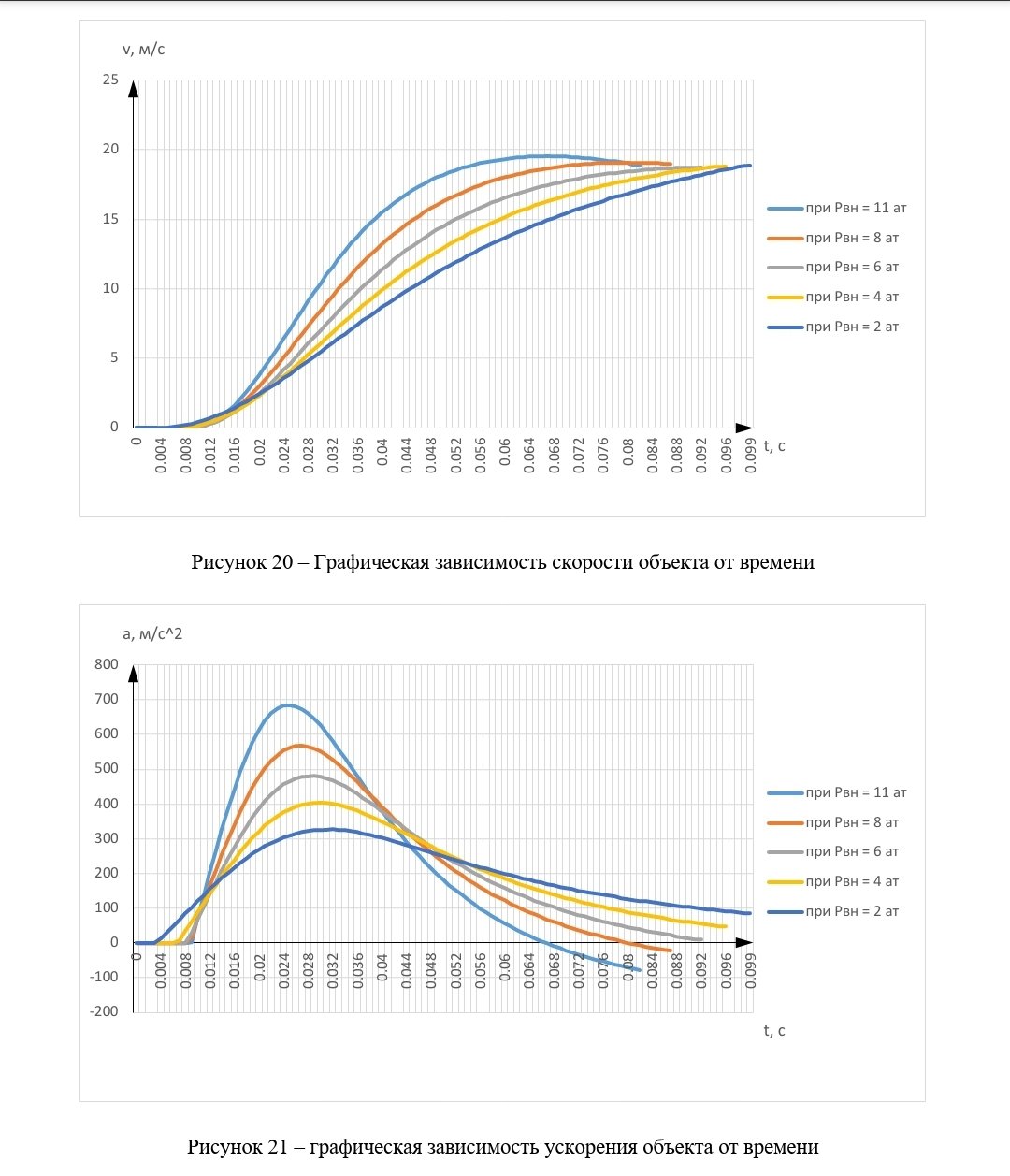
Figure 16 – Graphical dependence of pressure in the cylinder on time Figure 17 – Graphical dependence of pressure in the installation on time Figure 18 – Graphical dependence of mass flow on time Figure 19 – Graphical dependence of object displacement on time Figure 20 – Graphical dependence of the object’s speed on time Figure 21 – graphical dependence of the object’s acceleration on time
From the figures presented above, it can be concluded that when the value of the effective flow area of the valve cross-section varies over the entire range of ambient pressure values, with a decrease in external pressure, almost the same exit velocity of the object is observed and the values of the maximum longitudinal load do not exceed the allowable values.
The values of the output speed of the product and the maximum longitudinal overloads at the corresponding pressures of the external environment are presented in
Table 2. Also in fig. 22, a graphical dependence of these two parameters is plotted for convenient visualization of the results.
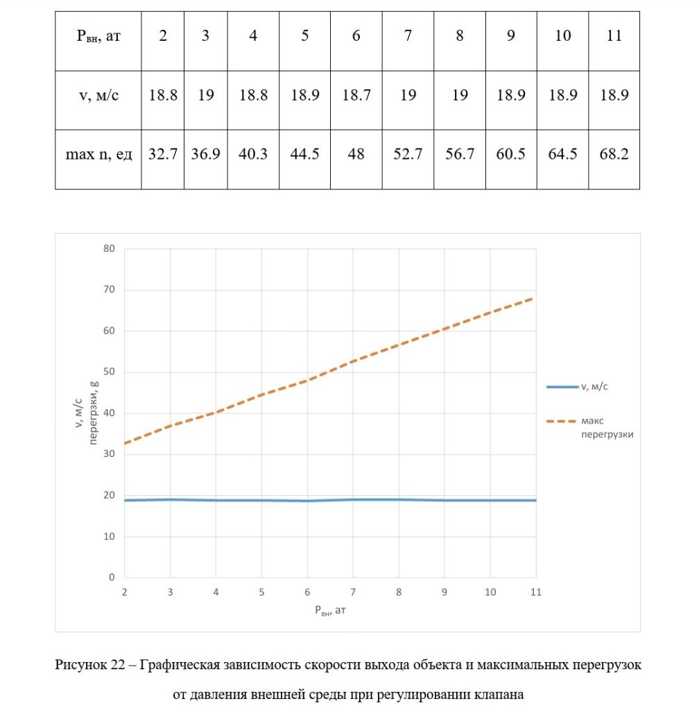
From the obtained values and graphic dependences, it can be concluded that even such a simple solution as controlling the effective area of the valve flow section makes it possible to achieve almost the same values of the object exit velocity and maximum longitudinal overload in the entire range of ambient pressures.
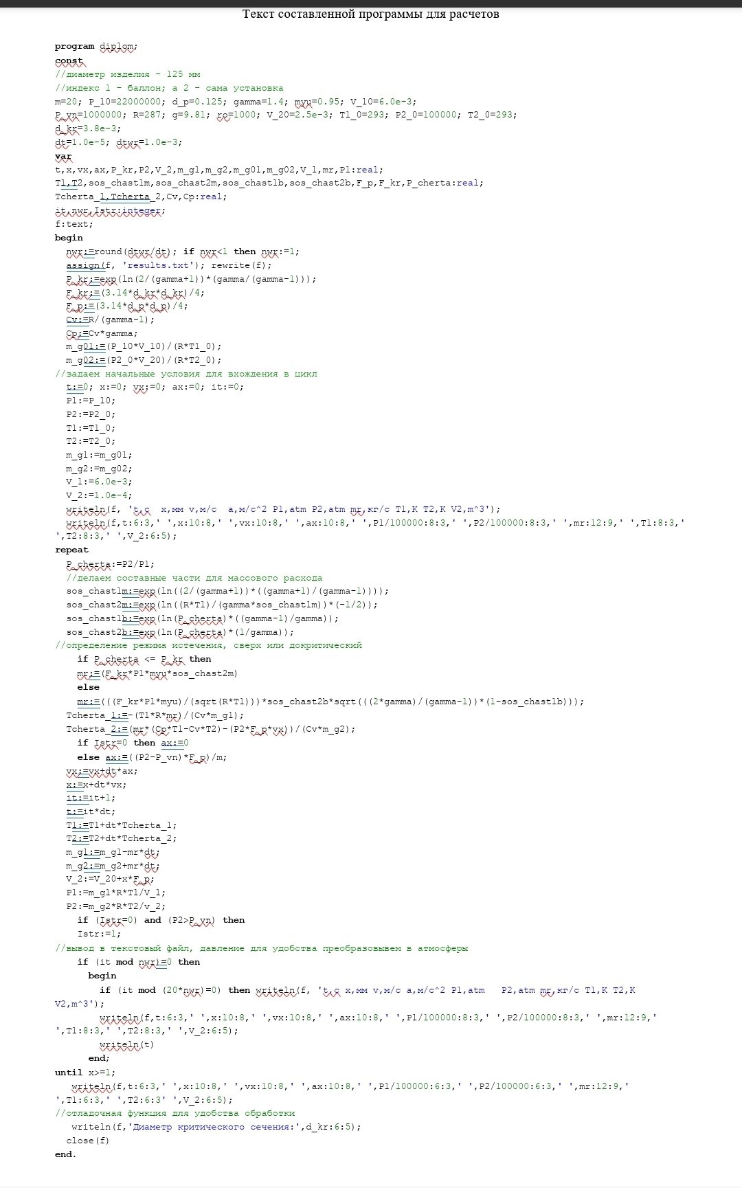
Conclusion List of used literature Annex A
The text of the compiled program for calculations
program diploma;


You must be logged in to post a comment.